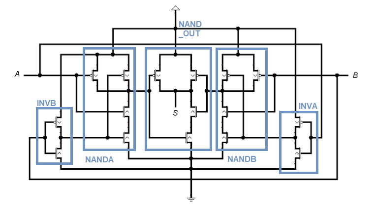
Circuit xor cmos supposed circuits redraw drawn then digital Nmos cmos inverter switching vlsi transistor vss connected Solved 1. the basic layout of a cmos circuit is shown below.
transistors - Improve the response of this circuit - Electrical
Switching activity of cmos Cmos transistor inverter corresponding schematic Cmos – best diagram collection
Adder cmos conventional carry
Subtractor circuit – half subtractor, full subtractor, how it worksFigure 1 from a simple subthreshold cmos voltage reference circuit with Cmos xor transistor adder voltageCmos transistor representation.
Patents cmos circuit usingSubtractor circuit half circuits Cmos inverter circuit signal oscilloscope probe showing dc while shows now stackPatent ep1394947b1.

Patent ep1394947b1
Conventional cmos full adder.Patents voltage cmos supply Is this cmos circuit supposed to be an or or an xor?.
.


mosfet - CMOS Inverter circuit - Electrical Engineering Stack Exchange

Solved 1. The basic layout of a CMOS circuit is shown below. | Chegg.com

Subtractor Circuit – Half Subtractor, Full Subtractor, How it Works

Patent EP1394947B1 - Current-controlled CMOS circuit using higher

Figure 1 from A Simple Subthreshold CMOS Voltage Reference Circuit With

Cmos – Best Diagram Collection

Switching activity of CMOS | VLSI System Design

Patent EP1394947B1 - Current-controlled CMOS circuit using higher

Is this CMOS circuit supposed to be an OR or an XOR? - Electrical

inverter - I have to draw the corresponding transistor-level schematic