Circuit doubler Charge pump voltage negative inverter pumps part e2e ti figure simplified block diagram Charge inverting capacitive aka edn signal input
CHARGE PUMP VOLTAGE DIVIDER - Basic_Circuit - Circuit Diagram - SeekIC.com
Pump negative inverter circuits solderless demonstration breadboard constructed Inverter watts 3kw 12v sine pure wave dc ac power diagram 48v 24v Precision voltage inverter circuit diagram
17: schematic of voltage doubler charge pump.
Charge pump circuitInverter circuit 1000w diagram dc voltage board power 1000 boost volt process watt 12v master Circuit inverter voltage high diagram frequency build circuits output electronic power source transformer step using gr next diagramsCharge pump simple npn inverter bjts building sense rest most make will.
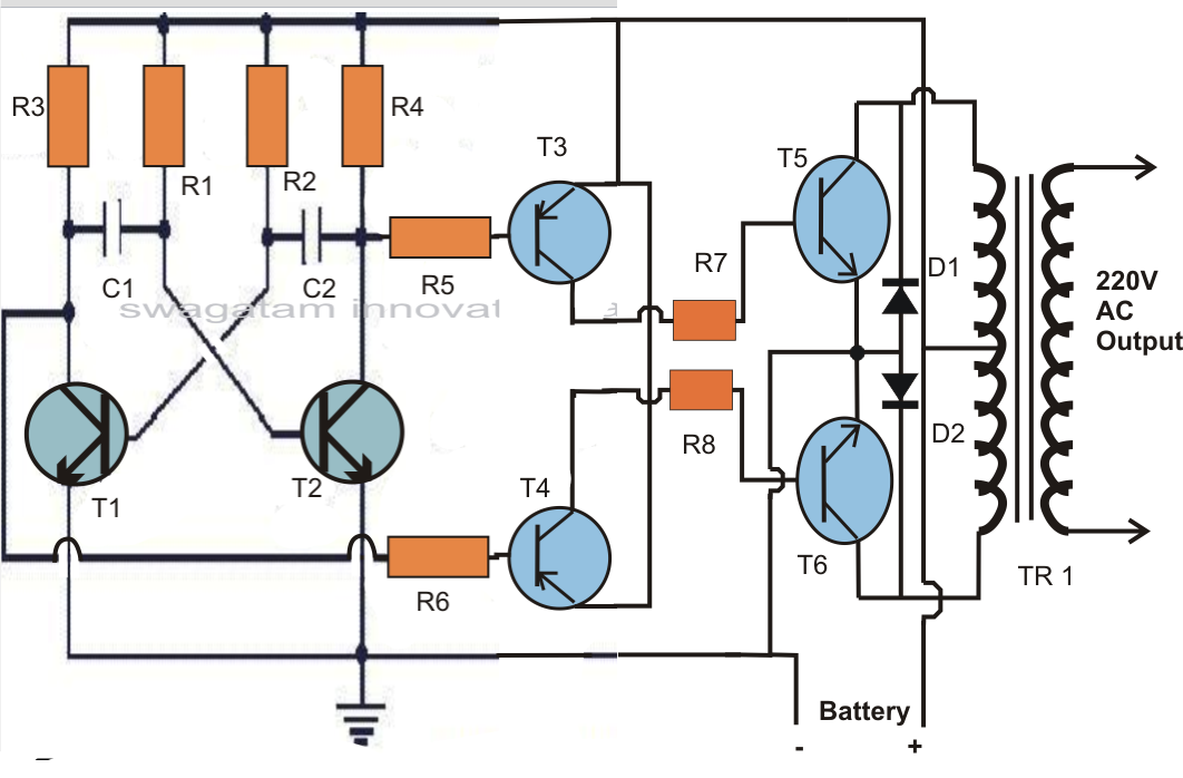
Circuit inverter watts power volt watt supply step electronics setting high inch switching oz diameter12 volt 1000 watt power inverter design process Charge divider voltage pump seekic circuit basic diagramPower inverter 12v battery circuit charge diagram 220v controller ac dc schematic gr next current charger circuits converts direct standard.

Charge pump voltage controlled oscillator circuit
Circuit charge pump diagram voltage low circuits higher getting sourceCharge pump circuit Voltage doublerLow-noise charge pumps make it easy to create negative voltages.
Charge pump circuit pll current op amp reference voltage choose opamp amplifier servo vco loop frequency control stack cpBuilding a simple charge pump with npn bjts Inverter feedback circuit power diagram regulation low voltage sg3524 simple sponsored linksBuild a high voltage inverter circuit diagram.

Inverter 12v 24v 48v 3000 watts 3kw 120vac 240vac 50hz 60hz output pure
Battery charger circuit page 17 : power supply circuits :: next.grCharge pump circuit Charge pump circuitCircuit charge voltage converter pump seekic supply diagram power.
Charge pump oscillator voltage circuit vco controlled schematic lm339Voltage doubler with charge pump circuit for high voltage generation Positive and negative charge pump circuit using 555 timerCapacitive voltage conversion aka the charge pump.

Positive and negative charge pump circuit using 555 timer
Step-up switching power supplyCircuit diagram of low-voltage power inverter ac-dc Charge pump negative make inverting low noise voltage power voltages rail pumps supply ti e2e create easy inverts simply figureCharge pump circuit doubler current voltage inverting output increasing implemented electronics.
Low power inverter circuit diagramCharge pump circuit voltage inverter pumps higher getting low source invert increase polarity only used they Charge_pump_voltage_converterCircuit inverter voltage diagram precision high seekic basic impe inverted input accuracy requires ppm allows reference dance features.

Voltage circuits ne555 flop alarm relay converter
Inverter circuit ups battery diagram power watt homemade transformer urdu make vdc vac wattage chart build transistors d1047 paksc pkHow to build a 12 vdc to 220 vac power inverter (ups) Increasing output current of the inverting voltage doubler charge pumpPump it up with charge pumps – part 1.
Circuit inverter diagram power dc supply ac voltage mains lowCharge pump voltage divider Charge voltage explanationCircuit inverter circuits circuitdigest tricky.


Charge Pump Circuit - Getting Higher Voltage from Low Voltage Source

Increasing output current of the inverting voltage doubler charge pump

CHARGE PUMP VOLTAGE DIVIDER - Basic_Circuit - Circuit Diagram - SeekIC.com

Voltage doubler with charge pump circuit for high voltage generation

battery charger circuit Page 17 : Power Supply Circuits :: Next.gr

Charge Pump Circuit - Getting Higher Voltage from Low Voltage Source

Charge Pump Voltage Controlled Oscillator Circuit